
In this project, we used opto-isolator modules to electrically isolate the parallel port output pins (pins 2 through 9) from whatever circuitry we decide to control with it. Each opto-isolator is a light-emitting diode and a phototransistor contained in the same 6-pin integrated circuit "chip." The only "connection" between the PC's parallel port and the electrical devices controlled by the phototransistors is the light beam emitted by the light-emitting diode. Thus, electrical mishaps cannot damage the PC's hardware:

When one of the parallel port output pins assumes a "high" state, it sends +5 volts to its respective opto-isolator LED, activating its phototransistor. The opto-isolator input circuit contains a green LED for visual indication of status, and is completed by a connection to one of the parallel port's several "Ground" pins (acting as the negative side of the voltage source for the LED). When the phototransistor activates, it is able to conduct current to a load device, being normally in the "off" state when not illuminated by the LED's light.
Our particular opto-isolator phototransistors are rated at an absolute maximum of 60 milliamps (that's 60/1000 of an amp, for the metrically challenged) load current. This is not much, being approximately the amount of current needed to energize three standard LED's connected in parallel, or perhaps a single miniature incandescent lamp. So, if you want to control any serious load current for things like electric motors, solenoids, large lights, sirens, etc., you must connect additional transistors to act as current-amplifying "buffers." Here is the "buffering" circuitry we used to let four of the parallel port output lines control a stepper motor:

Please note the diode (part number 1N4001) connected in parallel with the motor winding. It is there for a very important reason! Any load device possessing substantial inductance (the ability to store energy in a magnetic field) will create huge voltage surges when de-energized unless an alternate path for current is provided. If the diode were not in place, the motor coil's inductance would produce a surge of voltage every time the transistor turned off that would destroy the transistor, and perhaps the phototransistor inside the opto-isolator as well!
A single TIP30 power transistor was adequate for our stepper motor's needs, because each motor coil only drew about 1 amp. Thus, the power transistor only needed to amplify the opto-isolator's output current by a factor of 17 or so (1 amp divided by 60 milliamps). This amount of gain is very practical for a single transistor. If you plan to drive heavier loads, though, you will need more buffering than a single power transistor.
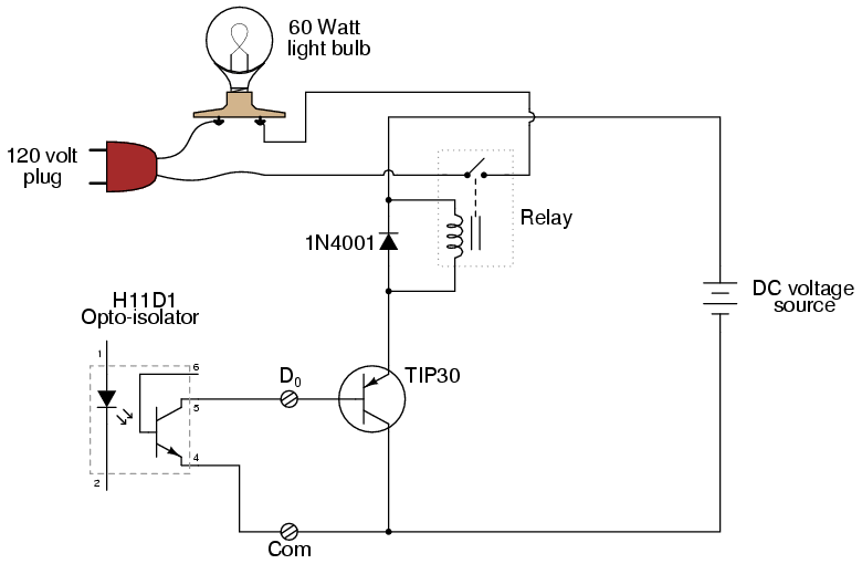
If you do not plan to switch your load on and off very frequently, an electromechanical relay will work nicely as a second buffering device. For example, the following circuit would work to turn a 60-watt, 120 volt light bulb on and off with one of the parallel port output lines:

In this particular case, the relay coil would have to function on one amp of DC current (or less), and be able to switch at least 1/2 amp of current at 120 volts AC at its contacts. There are plenty of small relays matching these criteria. Note that the diode is still necessary to prevent the relay coil's inductance from damaging the power transistor upon de-energization. Of course, the usual disclaimers of liability apply when you're wiring your own 120 volt circuits.
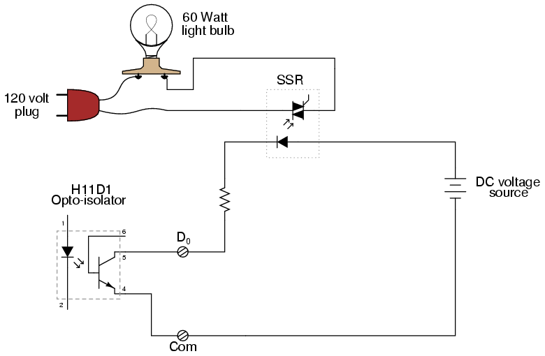
If fast on/off switching is what you need, you may build your own transistor buffer circuits, or purchase a "solid state relay" (SSR) module that functions as a large version of the small H11D1 opto-isolators:

Not only are most solid state relays capable of being driven with less than 60 milliamps of DC current (thus eliminating the need for a power transistor buffer), but they provide one more level of electrical isolation between the PC's parallel port and the 120 volt power circuit, which is a good thing. Expect to pay somewhere around $20 for a solid state relay, though.
Here is a link to a short MPEG movie of our parallel port interface box being tested. You can see the eight green LED's lighting up, one at a time.